Your Exponential Journey starts Today.
OpenExO is your gateway to becoming an Exponential Organization (ExO), empowering you to navigate and succeed in our rapidly evolving world.
orOpenExO is your gateway to becoming an Exponential Organization (ExO), empowering you to navigate and succeed in our rapidly evolving world.
or


Chat with AI-X, our ExO Bot, to find out more and how you can become an Exponential Organization. AI-X has all the knowledge that can be found in Exponential Organizations 2.0

Get exclusive access to a vast community of exponential thought leaders, innovation coaches, and disruption specialists. Tap into a wealth of knowledge and resources and learn how to apply the principles of Exponential Organizations. Gain valuable insights into the tools and strategies used by some of the world’s most successful companies.
Sign Up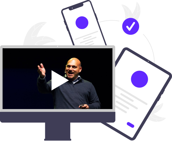
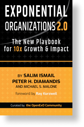
Discover the secrets of unparalleled growth with Exponential Organizations 2.0: The Playbook for 10x Growth & Impact, currently exclusively available to ExO Pass members.
Written by Silicon Valley legends Salim Ismail, Peter H. Diamandis, and Michael S. Malone together with more than 80 global OpenExO community members contains all new content from experiences gained in the 8 years since first publishing Exponential Organizations.
Our network of exponential thought leaders, innovation coaches and disruption specialists discuss and exchange the most profound changes and ideas in the world of business.

All your News in One Place. Explore countless articles, from thousands of sources curated for you into different topic subsections. No need to go anywhere else

Team Plan
2-99 Seats
The ExO Foundations Certification programme consists of four parts.
There are 9 videos, a quiz, an assessment and the completion of an Exponential Quotient Survey.
Contact UsOrganizations
100+ Seats
All of teams and
+ Live stats of staff completion + Data insights dashboard of EQS + Kickoff welcoming with Salim
Contact Us